INTRODUCTION TO TURBOMACHINERY

pages 29-33
A316 Derivation of equations of reference radii of blades A545 Calculation of internal work and pump input power A546 Calculation of internal work, losses and efficiency of steam turbine A706 Calculation of Laval turbine velocity triangles A936 Example of 2D calculation (shape of compressor inducer) A1266 Calculation of power output of turboset
Introduction to turbomachinery
page 2
Introduction to turbomachinery
page 3

Defining features of turbomachines

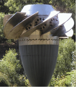
Blade machines are a wide group of machines (e.g. steam turbines, gas/combustion turbines, turbochargers, centrifugal/radial pumps, water turbines, etc.). Their characteristic feature is the rotor, which is a shaft with blades around its circumference (called an impeller). The blades form a so-called blade passages in which the working fluid flows - Figure 295 shows the rotor of a Kaplan water turbine, in which the blade passages are clearly visible.

295:
Kaplan turbine – rotor
Interaction between fluid and blades
The energy transformation occurs due to the interaction of forces between the working fluid and the blades. These forces are generated during energy transformations inside the blade passages, and in turbomachines, depending on the type, pressure, kinetic, potential or internal thermal energy can be transformed.
Turbines vs. working machines
If the working fluid transmits energy to the rotor, then the machine is called a turbine (the action force is from the flow of working fluid reacting from the blades) - the machine is doing work. In pumps, turbochargers, fans - working machines for short - the opposite process takes place and the working fluid gains energy (the action force is from the blades reacting with the fluid flow) - the machine consumes the work.
Number of blades vs. rotational speed
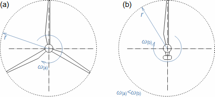
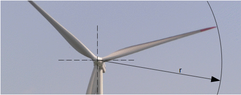
The blade passage principle also works for "sparse" rotors, or even with large blade spacing, as demonstrated by wind turbine rotors, see Figure 981 (p. 4). Even single-blade rotors can be constructed. In general, however, the smaller the number of blades, the higher the rotational speed for the same change of direction of velocity in the blade passage as a rotor with a larger number of blades but lower speed - only in this way can the flow over the entire rotor area be processed with the same efficiency.
Introduction to turbomachinery
page 4
981:
Wind turbine - rotor
ω [rad·s-1] angular velocity; r [m] rotor radius.

Operating principle of turbomachines

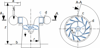
For turbomachines, a pressure difference upstream and downstream of the machine (pressure gradient) or a difference in the velocity of the working fluid or a combination of both is typical, as for example for a water Kaplan turbine, see Figure 270. This water turbine also contains blades outside the rotor, such blades are referred to as stator blades and their purpose is to direct the working fluid flow at the required angle and velocity towards the rotor blades. The stator blades also transforms part of the pressure energy of the water column above the turbine into kinetic energy. The stator (stator blades or Quide vanes) is contained in most types of turbomachinery.

270:
Energy transformation in Kaplan turbine
 Energy transformation in Kaplan turbine
a-reservoir level; b-tailwater level; c-stator (quide vanes); d-reinforcement of spiral casing (sometimes called volute). z [m] height difference between levels.
Introduction to turbomachinery
page 5
Turbocharger
An internal combustion engine turbocharger is a turbomachine with two rotors on a common shaft, see Figure 271 - one rotor is a turbine rotor and drives the compressor rotor, which compresses air for the engine. In this case, the exhaust gases from the engine enter the turbine rotor through two spiral casings which discharge into a bladeless stator which performs the same function as the blade stator in a Kaplan turbine, with the difference that during expansion, the exhaust gases are cooled, or in this case, part of the internal thermal energy of the exhaust gases is also transformed into work. In the compressor rotor, the inlet air is compressed and at the same time accelerated. At the outlet of the compressor rotor is a bladeless stator (diffuser) whose function is to move the air evenly away from the rotor and slow it down before entering the spiral casing – in this case, the air temperature increases during compression, or part of the work is transformed into internal heat energy of the air.
271:
Turbocharger
Turbocharger
a-turbine rotor; b-compressor rotor; c-double spiral casing of turbine; d-bladeless confuser; e-exhaust gases; f-air inlet; g-bladeless diffuser; h-spiral casing.
Wind turbine
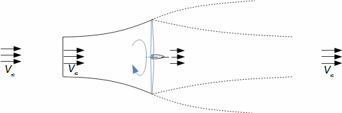
The kinetic energy of wind can be transformed into work using a wind turbine, see Figure 193 (p. 6). Wind turbines do not have a casing, but the airflow passing through the rotor creates a stream tube with a gradually increasing flow area as the airflow velocity decreases. Behind the turbine, the stream tube collapses because the air inside has lower energy than the surrounding air.
Introduction to turbomachinery
page 6
193:
Wind turbine
Wind turbine
V [m·s-1] wind velocity in front of affected turbine area.

Basic types of turbomachines

The design perform of turbomachine is mostly influenced by the properties of the working fluid, more precisely its compressibility, which is why we divide turbomachines into hydraulic and thermal machines. For hydraulic machines (pumps, water turbines, fans, wind turbines etc.) the change in the density of the working fluid is largely insignificant. For heat machines (compressors, steam turbines, gas turbines etc.) the density of the working fluid changes significantly.

  ~  
Rotodynamic pumps
Pumps operating on the principle of the turbomachine are called turbopumps or hydrodynamic pumps. Pumps are machines used to transport and pressurize liquid. Rotodynamic pumps can be divided into circulating, condensate and feed pumps according to the operating conditions.
Circulation pumps
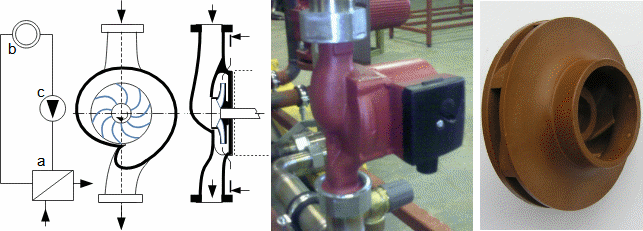
Circulation pumps are mainly used to circulate liquid in the loop - overcoming pressure losses in the loop. The energy transferred to liquid in circulation pumps is approximately 100 J·kg-1. The power input can be up to units of MW (the main circulation pump of a nuclear power plant). Figure 292 (p. 7) shows an example of a small criculation pump with a centrifugal or radial rotor in a monoblock design, which is connected in a loop with a heat exchanger and a heat consumer. The fluid in the rotor, by centrifugal forces, flows from the centre of the rotor to its circumference. From the rotor, fluid exits into a spiral casing where it is discharged to the discharge end of the pump.
Introduction to turbomachinery
page 7
292:
Circulation pump
Circulation pump
a-heat exchanger; b-heat consumer; c-circulation pump. The rotor is made of PPS (Polyphenylsulfide).
Condensate pumps
Condensate pumps are designed to pump liquids close to the saturation point (e.g. condensate and liquefied gases). The energy transferred to liquid in a condensate pump is higher than in circulation pumps (500 J·kg-1 in the case of water) because the condensate is pumped to higher pressures.
Feed pumps
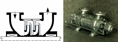
Feed pumps are characterized by pumping liquid to high pressures, where the energy transferred to liquid reaches up to several tens of kJ·kg-1 - in order to transfer this amount of energy to liquid, several rotors are required in succession, in such cases we speak of a multi-stage turbomachine, see Figure 293.
293:
Multi-stage pump
Multi-stage pump
Pictured is a pump from Sigma Hranice.
  ~  
Water turbines
Water turbines are among the most powerful types of turbomachinery with outputs up to 1000 MW. Three types of water turbines are most commonly used: the Pelton turbine, the Francis turbine, and the Kaplan turbine. A water turbine needs a specific minimum difference in levels or pressures.
Pelton turbine
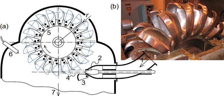
In Pelton turbines, the potential energy of water is first transformed into kinetic energy in the nozzle in front of the rotor. The jet of water from the nozzle spins the rotor as it contacts its blades, where it transfers its kinetic energy to them, see Figure 530 (p. 8).
Introduction to turbomachinery
page 8
530:
Pelton turbine
Pelton turbine
(a) basic parts of Pelton turbine; (b) rotor of Pelton turbine with diameter 850 mm and power 980 kW - this turbine is part of Temelín nuclear power plant, from which waste water is fed through pipe 6.47 km long and 700 mm in diameter, turbine's machine room is at level of Vltava river at Kořensko hydroelectric power plant, author of photograph is Jiří Kohout. 1-inlet from ball valve; 2-control needle; 3-deviator of water jet; 4-water jet; 5-blades; 6-braking nozzle (reduces turbine run time during shutdown); 7-water outlet from rotor.
Francis turbine
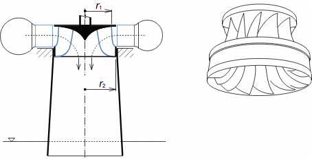
Francis turbines is similar to Kaplan turbines. There is pressure corresponding to the water head in front of the stator blade cascade. In the stator, the water flow accelerates (due to the narrowing of the passages created by the stator blades) and the pressure drops. The water stream inlets the rotor blade passages, which spin the rotor. The stator blades are rotatable, which allows power control, see Figure 1263. The rotor blades of Francis turbines are fixed, so the blade passages shape cannot be changed by turning the blades as in Kaplan turbines, see Figure 295 (p. 3).
1263:
Francis turbine
Francis turbine
 
  ~  
Fans
Fans are used for transport and for a small increase in gas pressure at which there are no significant changes in density. According to the increase in total pressure, fans are divided into low pressure (0 to 1 kPa), middle pressure (up to 3 kPa) and high pressure (above 3 kPa).
Introduction to turbomachinery
page 9
Low pressure radial fan
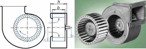
Figure 261 shows a section of a low pressure radial fan with forward curved blades with a spiral casing. In this case, only the working gas velocity is increased in the rotor, since the blade passages have the constant flow area, the working gas pressure can be increased in the diffuser passage connected behind the outlet of the spiral casing.
261:
Radial low pressure fan
b [m] width of rotor; h [m] width of spiral casing. Photo: ebmpapst, casing cast in aluminium alloy.
  ~  
Wind turbines
Machines without casings containing only the rotor are also called vortex machines because there must be a vortex behind the rotor. Machines without the casing include wind turbines (Figure 299), aircraft propellers or ship propellers. Machines without the casing can only carry out small changes in pressure because this would lead to instability of the rotor stream tube, see Figure 193 (p. 6).
299:
The rotor of Vestas V90 wind turbine with the column height of 105 m, the rotor diameter of 90 m and the nominal power of 2 MW. Drahany (CZ).
Wind turbine
  ~  
Turbocompressors
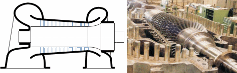
In turbocompressors, the compression of gases or vapours takes place, or an increase in pressure energy and, if the compression is not cooled, an increase in internal thermal energy due to an increase in temperature. The kinetic energy of the gas is transformed into enthalpy in the diffuser blade passages. For higher compression, multi-stage turbocompressors are used, see Figure 298 (p.10).
Introduction to turbomachinery
page 10
298:
Multi-stage turbocompressor
General Electric Company.
  ~  
Steam turbines
In steam turbines, vapour (usually steam) expands to a lower pressure while its enthalpy is transformed into work. Steam turbines are used to generate electricity in thermal and nuclear power plants and in industrial plants with a steam source.
Steam expansion
Figure 296 shows a section of a Laval steam turbine, in order to describe its function. Steam from state 0 expands to state 1 in the stator in the form of the Laval nozzle, in which enthalpy is transformed into kinetic energy. The steam stream then enters the rotor blade passages in which the kinetic energy of the steam is transformed into work. The work done is therefore the difference of the kinetic energies in front of and behind the rotor.
296:
Laval turbine (single stage steam turbine)
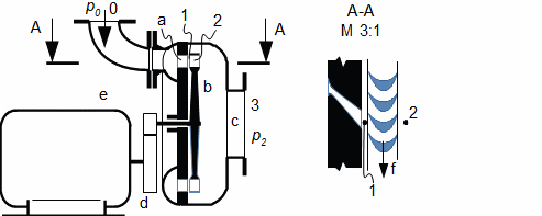
a-nozzle (there may be several nozzles around the circumference for higher flow and power); b-rotor; c-outlet; d-gearbox; e-el. generator; f-direction of rotor rotation. 0-steam inlet; 1-space between rotor and nozzle; 2-steam outlet from rotor; 3-steam outlet, p [Pa] pressure.
Multi-stage steam turbine
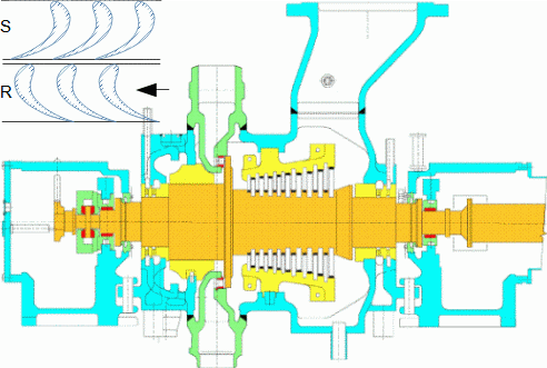
Larger enthalpy differences are more advantageously processed by multiple stages in a multi-stage turbine. Each stage contains a stator row of blades attached to the casing (forming a series of nozzles spaced around the perimeter) and a rotor row of blades, see Figure 170 (p. 11).
Introduction to turbomachinery
page 11
170:
6 MW 10-stage steam turbine
10-stage steam turbine
9980 min-1, inlet parameters: 36,6 bar, 437 °C, outlet steam pressure 6,2 bar. S-stator blade row; R-rotor blade row. Alstom, provenance Brno (CZ).
Multi-casing turbines
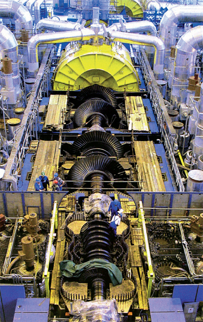
Large power turbines are divided into several smaller turbines (casings) - this solves the problem of large bearing distances in the case of multi-stages or the problem of large volume flow. The turbine casings are arranged in series connected by couplings, or side by side without couplings, and the steam distribution between the bodies can be in series or parallel, such turbines are called multi-casing turbines, see Figure 297 (p. 12).
Introduction to turbomachinery
page 12
297:
Four-casing steam turbine at Temelín Nuclear Power Plant
 Four-casing steam turbine at Temelín Nuclear Power Plant
The length of turboset is 63 m, it means leght including generator, the length of the rotor is 59,035 m (turbine rotor 36,45 with weight of 240 t) and its weight 326,4 t (2000 t is total weight of turboset), of which 93 t weighs the rotor of one low-pressure part. 1x highpressure casing; 3x lowpressure casings. The last casing of turbine is closed. Made by Škoda (CZ).
  ~  
Gas turbines
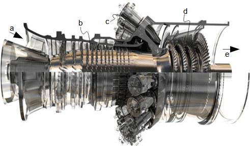
The working fluid of gas turbines is gas or flue gas. The most commonly used are combustion turbines with a combustion chamber. Combustion turbines contain a turbocompressor section and a turbine section. Figure 133 (p. 13) shows a section of a combustion turbine. The turbocompressor compresses the inlet air. In the combustion chamber, combustion of the fuel and compressed air takes place. The combustion produces hot exhaust gases (gas) which drive the turbine section. The power of the turbine section is used to drive the turbocompressor (most of the power) and also an electrical generator or other equipment.
Introduction to turbomachinery
page 13
133:
Combustion turbine GE-9F series
a-air inlet; b-compressor stages; c-combustion chambers; d-turbine stages; e-exhaust gas outlet. Output power 300 MW.
Turbojet engines
Combustion turbines are also used to drive turbojet engines - in this case, the power of the turbine section is equal to the power input of the turbocompressor, and the rest of the enthalpy gradient contained in the exhaust gas is used for expansion in the engine nozzle and creates thrust on the reaction principle.

Nomenclature of meridional flow direction

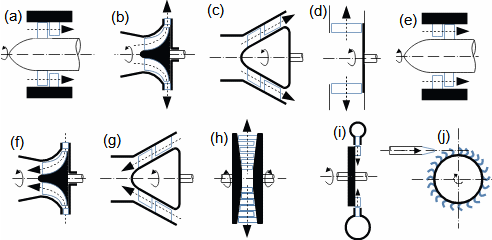
Classification of turbomachine stages by the stream direction in relation to the axis of the shaft (Figure 276 – four main directions or meridional directions: axial, radial, mixed and tangential) informs about design of the machine. The predominant flow direction is usually reflected in the machine name.

276:
Stages of turbomachines according to meridional flow direction
Introduction to turbomachinery
page 14
(a) to (d) are pumps, compressors or fans; (e) to (j) are turbines. (a) axial; (b) radial – with axial inlet; (c) mixed flow; (d) radial – flow (centrifugal); (e) axial; (f) radial – with axial outlet; (g) mixed flow; (h) radial – flow (in case with alternate rotors rotating opposite); (i) radial – flow (centripetal); (j) tangential – (e.g. Pelton turbine).
Specific speed
Each direction of flow gives the individual turbomachine stages different characteristics and the most suitable type for a given application is therefore determined by its specific speed and operating parameters.

Construction features of turbomachines

Turbomachines contain flow and machine parts. In addition to the rotor, most turbomachines also contain inlet and outlet flow parts (branches), casing, bearings, shaft seals, etc. They often have fluid quality and quantity control. Figure 189 is a section of a Kaplan turbine that contains most of these parts.

189:
Structural parts of Kaplan turbine
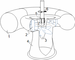
1-inlet of water into turbine through spiral casing (inlet branch); 2-stator blades (adjustable for flow control); 3-rotor (adjustable blades for efficiency control); 4-draft tube (outlet part or outlet branch); 5-radial bearing (captures forces perpendicular to axis of rotation); 6-axial bearing (captures forces parallel to axis of rotation); 7-rotor seal (shaft passage through casing).

Blades

Blades are most often manufactured individually and are inserted into the rotor and stator in a single row. The blade row is also referred to as the blade cascade. Blades are attached using their roots or by other methods. The representation of the cylindrical section on a certain radius of the blade cascade is referred to as a profile cascade and the shapes of the blade passages are clearly visible.

Introduction to turbomachinery
page 15
  ~  
Blade cascade
The blades in the blade casacde create a row of passages of the required dimensions and shapes, see Figure 194. Some turbomachines have adjustable blades (this allows the size of the flow passage to be changed or completely closed), e.g. the Kaplan turbine. In some cases a shroud is placed on the blade tips.
194:
Example of rotor disc structure of single-stage steam turbine (Laval turbine)
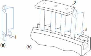
(a) blade; (b) formation of passages by using blades (blade passage); 1-blade root; 2-shroud (not necessarily); 3-spacer.
  ~  
Blade roots
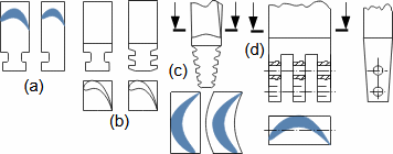
The blade root (Figure 953) fixes the blade in the rotor or stator and captures the forces acting on the blade, which are mainly centrifugal force and the forces on the blades from the fluid flow (the root type Figure 953d bears the greatest load). The root must also have a good damping function. Smaller natural frequencies of oscillation have roots that also integrate the spacer (a part that is inserted between adjacent blades to keep them at the required distance from each other), or even several blades are integrated on one large root (made of one piece or several blades and roots are welded together, etc.). The root must be resistant to fatigue failure to prevent it from loosening from the grooves over time.
953:
Basic types of blade roots
(a) examples of blade roots shapes common in drawn blanks; (b) single T-root and double T-root typical of milled profiles (mainly used in drum rotors); (c) tree root (this type and type (c) are used in disc type rotors); (d) multi-finger pinned root. Blades with root types (a) and (b) are inserted tangentially into the rotor grooves as indicated in Figure 194, blades with root type (c) are inserted axially into the disc.
Introduction to turbomachinery
page 16
  ~  
Profile cascade
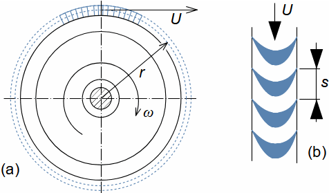
A section through the blade cascade is called the profile cascade (see Figure 1261). As can be seen from the profile cascade, the size of the blade passages, respecitvely the distance between blades, or pitch, depends on the radius at which the cut is made. In this case, the blades are short relative to the diameter and the change in dimensions is not apparent; it is a so-called straight blade. For higher efficiency, especially for longer blades, so-called twisted blades are used - their shape and size change along their length (e.g. Figures 295 (p. 3), 298 (p. 10), 299 (p. 9)). Straight blades are often used in radial machines or as short blades in axial machines.
1261:
Laval turbine rotor disc
(a) turbine rotor mounted with blades; (b) developed cylindrical section through blade passages at radius r (profile cascade). r [m] mean radius of blades; s [m] pitch of blades; U [m·s-1] blade speed at radius r.
Description of blade Profile
Figure 195 shows names of the individual profile parts, which depend on the shape and orientation of a profile in the cascade. We refer to the inlet edges of the profiles as leading edge LE and the outlet edges as trailing edge TE. Along the curved surfaces of the profile, the pressure varies (see Aerodynamics of airfoils [Škorpík, 2025]) - we refer to the side of the profile with lower pressure as the suction surface of the profile SS and the side with higher pressure as the pressure surface of the profile PS.
195:
Basic nomenclature of blade profile
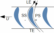
LE-leading edge; TE-trailing edge; SS-suction surface; PS-pressure surface. u [m·s-1] blade speed at given blade radius.
Introduction to turbomachinery
page 17

Energy balance of turbomachine

One of the main parameters of turbomachines is their internal power. Internal power is the power of the working fluid flowing through the turbomachine and is defined as the product of its internal work and mass flow, see Equation 289. However, so-called internal losses arise during the transformation of the energy of the working fluid into internal work. The quality of the transformation of the energy of the fluid into internal work is determined by a quantity called internal efficiency.

289:
Internal power of turbomachine
Pi [W] internal power/power of turbomachine; wi [J·kg-1] internal work of turbomachine;  [kg·s-1] mass flow of working fluid through turbomachine. If the working fluid consumes the work (working machine), the work will be negative and hence the value of Pi, but usually the negative sign is not given and the expression "power input" is used.
  ~  
Internal work
To calculate the internal work of the turbomachine, the equation of the first law of thermodynamics for open system can be used, see Equation 288. This equation takes into account all the energy transformations in the working fluid that can occur in the turbomachine - it can do/consume work, it can be heated or cooled (heat can be shared with the working fluid through the walls of the machine or heat can be released in the working fluid e.g. by a chemical reaction), so the enthalpy, kinetic and potential energy of the working fluid can change.
288:
First law of thermodynamics for open systems
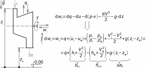
ρ [kg·m-3] density; g [m·s-2] gravitational acceleration; u [J·kg-1] internal thermal energy; q [J·kg-1] heat transfer with surroundings (positive value: heat is delivered to machine; negative value: heat is rejected from machine); h [J·kg-1] enthalpy (static); hs [J·kg-1] stagnation enthalpy of fluid; ep [J·kg-1] potential energy of working fluid; T [N·m] torque on shaft. The index i indicates the input, the index e the output of the machine. This scheme of energy balance of an open system is taken from the article Engineering thermomechanics [Škorpík, 2024].
Introduction to turbomachinery
page 18
Internal work of Hydraulic machines
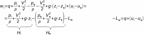
A special form of the first law of thermodynamics for incompressible fluids is called the Bernoulli equation, see Equation 543, and is used for calculating hydraulic machines. In this case, only pressure, kinetic, and potential energy transformations are acceptable, and transformations of other types of energy are considered as internal losses-hence the sum of the pressure, kinetic, and potential energy of the liquid is called a head of liquid.
543:
Bernoulli equation
Bernoulli equation
H [J·kg-1] head; Lw [J·kg-1] internal losses on machine work.
Internal work of Heat machines
In heat machines, any kind of energy can be transformed, but the effect of potential energy changes is usually insignificant. Also, the effect of changes in the pressure energy and the internal thermal energy of the working fluid is not distinguished, and instead one operates with the quantity enthalpy, so that the First Law of Thermodynamics for open systems is used for these cases in the form of Equation 544.
544:
Specific internal work of heat turbomachine
  ~  
Internal losses of turbomachine
The transformation of energy in turbomachine induces internal losses denoted by an symbol Lw. The internal loss is the portion of the energy transformed to other than the required energy and arises, for example, from internal friction of the working fluid, mixing of cold and hot streams, heat exchange between streams, swirling, etc. The internal loss is reflected by a larger value of the internal thermal energy (enthalpy) and entropy of the working fluid at the machine outlet, compared to the case of ideal energy transformation in the turbomachine, see Problem 546 (p. 19). This means that the internal losses are the difference between the ideal internal work of the machine and the actual internal work of the machine, see Formula 1265 (p. 19), where the internal ideal work of the machine is the work of the machine without internal losses (hence the index w at the letter L). The ideal work of hydraulic machines corresponds to the value of the change in the head of the fluid (wiH). The ideal work of thermal machines is usually isentropic wis or polytropic reversible change wpol.
Introduction to turbomachinery
page 19
1265:
Internal losses of turbomachine
wid [J·kg-1] ideal internal work of turbomachine.
  ~  
Internal efficiency
The internal efficiency ηi defines the efficiency of energy transformation inside the machine by comparing the actual internal work of the machine wi with the internal ideal work of the machine wid, see Formula 604(a, b).
604:
Internal efficiency of turbomachine

(a) internal efficiency of turbines; (b) internal efficiency of working machines. ηi [1] internal efficiency.
Special terms
It is customary to refer to the internal efficiency of hydraulic machines as hydraulic efficiency and that of heat machines as internal thermodynamic efficiency. The word "internal" is omitted for wind turbines and propellers.
Application of energy balances
The above special equations can be used in the design of a machine or its stage, for complete energy balances of technological units as well as for approximate calculations of basic machine parameters, as shown in Problems 545 and 546.
Problem 545/1:
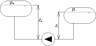
20 t·h-1 of water is pumped from a lower tank to an upper tank by a turbopump. The pressure in the lower tank is 1 bar, the pressure in the upper tank is 40 bar, the difference in level is 7 m. What is the approximate internal work and the approximate internal power input of the pump? The solution of this problem is shown in Appendix 545.
Problem 545/2:
Problem 546/1:
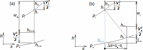
Steam enters a steam turbine at the pressure of 36.6 bar and the temperature of 437 °C. The pressure at the turbine outlet is 6,2 bar and the internal work of the turbine is 410 kJ·kg-1. Find the internal losses and the internal efficiency of the turbine - the turbine is thermally well isolated (q≈0), so the comparative ideal process is isentropic expansion. The solution of this problem is shown in Appendix 546.
Introduction to turbomachinery
page 20
Problem 546/2:
h-s chart of steam turbine
(a) changes in steam state during isentropic expansion; (b) changes in steam state during actual expansion. s [J·kg-1·K-1] entropy. The index is denotes isoentropic change.

Turboset

Turbomachines are always connected to another machine (e.g. turbine/generator, pump/motor, etc.). Machine assemblies with a turbomachine are called turbosets, see Figure 221.

221:
Turboset of Kaplan turbine and turbogenerator
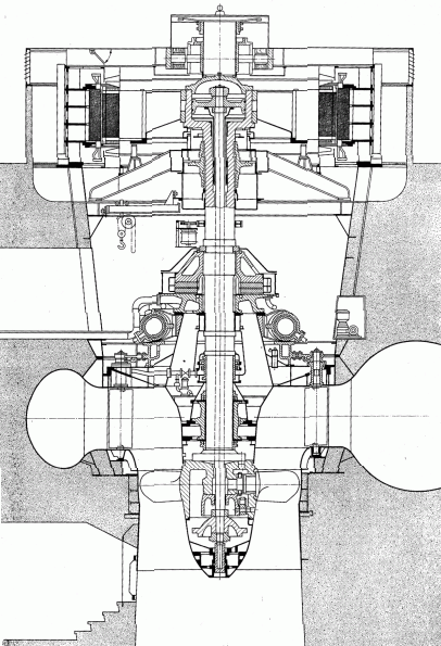
Manufactured by Voith [Miller et al. s. 591].
Introduction to turbomachinery
page 21
Energy balance of turboset
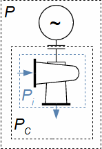
Figure 1027 shows a typical schematic of the turboset containing, in addition to the turbomachine, a gearbox and an electric generator. This figure also shows the indicated power in the individual parts of the machine, which is progressively reduced from the internal power of the machine (the power of the working fluid in the flow section) by losses in the individual parts of the turboset, see Problem 1266.
1027:
Turboset efficiency and power input/output
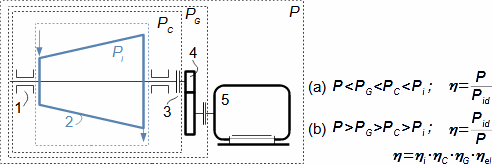
(a) power of tuboset; (b) power input of turboset. 1-machine bearing; 2-machine interior; 3-coupling; 4-gearbox; 5-generator/drive. PC [W] input/output power at coupling; PG [W] input/output power of gearbox; P [W] input/output power at generator/drive contacts; Pid ideal tuboset power - all energy transformations in turboset are lossless; η [1] turboset efficiency; ηC [1] turbomachine mechanical efficiency; ηG [1] gearbox efficiency; ηel [1] generator/drive efficiency.
Problem 1266/1:
Calculate the power output of a water turbine generator. The internal power of the turbine is 15 MW, the efficiency of the turbine at the coupling is 97,5 %, the efficiency of the generator is 97 %. The solution of the problem is shown in Appendix 1266.
Problem 1266/2:
Turboset with water turbine and electric generator
Turboset label
The parameters of the turboset are indicated on its label. This label shows the nominal power Pn (reference power, usually maximum) and the optimum power Popt at which the machine achieves maximum efficiency.
Agreement parameters
The indication of the efficiency of the turboset and its power is an important agreement parameter. Equally important are the efficiencies of the individual components of the turboset for the agreement between the subcontractors and the final contractor of the turboset, in order to trace which of the subcontractors failed to meet the technical criteria if the turboset as a whole did not meet the parameters in the agreement.
Introduction to turbomachinery
page 22

Turbomachine stage

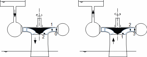
The turbomachine stage contains the stator (stator cascade of blades) and the rotor (rotor cascade of blades). The Francis pump turbine stage (reverse turbine) is shown in Figure 192 as an example of the turbomachine blade stage composition. The turbine stage is made up of first the stator row of blades then the rotor row, the reverse is true for the working machines.

192:
Turbomachine stage
Turbomachine stage
Marking of working fluid states
The energy of fluid can only be transformed into work in the rotor, therefore index 1 in front of the rotor and index 2 behind the rotor is used for the working fluid state. In turbines, the fluid state in front of the stator is denoted by index 0. For working machines, the fluid state behind the stator is indicated by index 3. For multi-stage machines, the method of marking within the stage is identical, see Figure 277.
277:
Example of working fluid state marking on multi-stage turbomachine
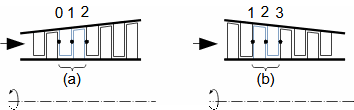
(a) turbine stage; (b) turbocompressor stage.

Velocity triangle

In Equations 543 and 544 (p. 18) of the energy balance applied to the stage, the velocities V in front of and behind the blade row stand out. The fluid velocity V is called an absolute velocity and can project in three directions in a fixed coordinate system. The absolute fluid velocity V is the vector sum of the relative fluid velocity W and the blade speed U on the investigated blade radius. A graphical representation of the absolute and relative fluid velocity and blade speed is called a velocity triangle.

Introduction to turbomachinery
page 23
  ~  
Components of absolute velocity
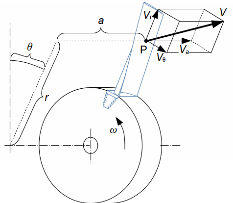
In the case of turbomachine, the cylindrical coordinate system is used to denote velocity components, which is clearer than the rectangular coordinate system for describing motion about an axis, as shown in Figure 861. The component of velocity perpendicular to the axial direction is called radial-r, the component of velocity in the direction of rotation is called tangential-θ, and the component of velocity in the direction of the axis is called axial-a. The absolute velocity is therefore the vector V(Vr, Vθ, Va), in the following the arrow denoting the vector is not shown for clarity.
861:
Absolute velocity in cylindrical coordinate system
Absolute velocity in a cylindrical coordinate system
P-point at which investigated velocity V; θ [°] azimuth.
Example of absolute velocities around rotor of turbocharger turbine
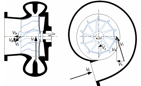
Figure 272 shows an example of the absolute velocities of the working gas in front of and behind the rotor of a turbocharger turbine and their components according to the proposed orientation of the cylindrical coordinate system.
272:
Example of absolute velocities around rotor of turbocharger turbine
Introduction to turbomachinery
page 24
  ~  
Relative velocity
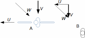
The relative fluid velocity W is the fluid velocity observed by an observer moving with the rotor of the stage. The relative velocity can have three spatial components. In order to clarify the concept of relative velocity, there is the Figure 257 showing a moving cyclist-A at speed U and a stationary observer-B. While the stationary observer observes the absolute direction and magnitude of the wind V, the cyclist observes the direction and magnitude of the wind W, which we refer to as relative, i.e., relative to the moving point with respect to the reference (stationary) point.
257:
Relative velocity
Relative velocity
U [m·s-1] cyclist speed; W [m·s-1] relative wind velocity.
  ~  
Blade speed
The blade speed is defined as the product of the radius of rotation r and the angular velocity ω (see Equation 548) and has no components in the axial and radial directions. The blade speed lies in the plane perpendicular to the axial direction.
548:
Blade speed
N [s-1] rotational speed.
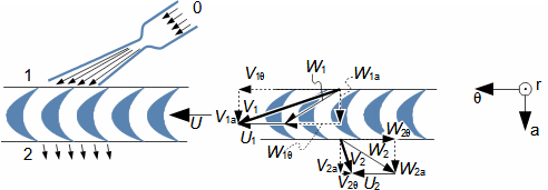
Example of velocity triangle: Laval turbine
Figure 273 shows velocity triangles for the rotor of the Laval turbine of Figure 296 (p. 10), where the working fluid (steam) inlet to the rotor blade passages is at velocity V1 and outlet at velocity V2.
273:
Velocity triangle of Laval turbine rotor
Angles in velocity triangles
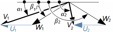
The velocity triangle is not usually drawn together with the profile cascade, but is shown separately for clarity and calculation purposes. The angles of the individual velocities are also plotted, as shown in Figure 549 (p. 25), which also presents additional rules for its construction. For example, the inlet and outlet velocity triangles are drawn in the plane of the flow. The positive direction of the individual velocity components is in the direction of the blade speed. The angles are quoted counterclockwise for ease of calculation using goniometric functions, but other quoting of angles is possible.
Introduction to turbomachinery
page 25
549:
Velocity triangle
Velocity triangle
α [°] angle of absolute velocity; β [°] angle of relative velocity.

Design of turbomachine stage

When calculating the stage of the turbomachine, the values and directions of the velocities in the velocity triangle are important for the design of the shape of the blade passages, respectively the blades - if the direction is known, the camber of the passages can be designed, if the change in velocity is known, it can be designed whether the passage should be narrowed or widened, etc. The velocity triangle is valid for a specific point under investigation in the working fluid volume in the machine. A neighbouring point will already have a slightly different velocity triangle, so when designing the turbomachine stage, we approach a certain level of simplified flow description according to the design accuracy requirement. Depending on the level of simplification we talk about 1D, 2D and 3D calculation.

  ~  
1D calculation
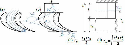
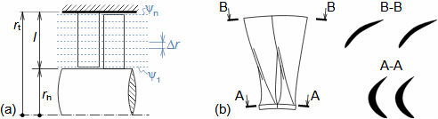
In 1D calculation, the actual spatial velocity field in the blade passage is replaced by a single reference streamline with a mean flow velocity, see Figure 316a. The reference streamline passes through the centre of the blade passage and is located at the mean or square radius of the blade as decided by the designer, see Figure 316b. Many simplifications are introduced in the calculation so that the calculation is simple but sufficiently representative over the entire volume of the stage. It is used when designing the blade passage shape of a machine with straight blades, i.e. where the blades are short and there is no significant difference in blade speed between the root and tip, see Problem 706 (p. 26).
316:
Diagram of 1D flow through stage at mean radius
Introduction to turbomachinery
page 26
(a) actual flow in blade series; (b) simplification to 1D flow; (c) equation for mean radius of blades; (d) equation for mean square radius of blades (mean square radius is radius at which area between rt and rm is as large as area between rm and rh). l [m] blade length; Δβ [°] required camber of flow. ψ-streamline. The index ref denotes reference, t radius of the blades at the tip (tip), h radius at the base of the blades (hub), index m denotes mean. The derivation of the mean square radius equation is shown in Appendix 316.
Mean velocity
The mean velocity in blade passages can be determined from the continuity equation, or from the mean value of the kinetic energy of the working fluid in the passage, see the definition of mean velocities in the article Internal fluid friction and boundary layer development [Škorpík, 2023].
Problem 706/1:
Find the velocity triangle of a Laval turbine at the mean radius of the blades, which is 80 mm. The rotational speed is 29 625 min-1. The other parameters of the velocity triangle at the central radius are U1=U2, V1=530 m·s-1, V=0 m·s-1, W1=W2. The solution of the problem is shown in Appendix 706.
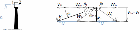
Problem 706/2:
Laval turbine velocity triangle
 
  ~  
2D calculation
2D calculation follows a similar procedure as in the previous case (replacing the actual flow field with a mean velocity flow streamline), except that the calculation of the velocity triangles are performed on several radii, see Figure 329a. This calculation method is mainly used in the calculation of turbomachinery stages, with the emphasis on achieving the best possible shape of the blade passage respecting the spatial character of the flow (increasing the pitch with the investigated radius and increasing the blade speed). The calculation is the basis for the shape of the blade passage at each radius of the twisted blades, see Figure 676b (p. 27), or of the blades of radial stages with axial part, see Problem 936 (p. 27).
329:
Elementary stage of turbomachine
Introduction to turbomachinery
page 27
(a) division of blade into n computational elements - calculation on specific radius is therefore called elementary stage of turbomachine; (b) example of changes in shape of blade passage between root and tip of twisted blades - both pitch and shape of blade passage changes according to results of velocity triangles for given elementary stage. n [-] number of elements; Δr [m] element height of stage.
676:
Examples of twisted steam turbine blades
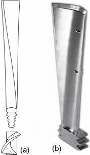
(a) change in shape of twisted blade designed to take into account spatial character of flow in the stage; (b) example of twisted blade of steam turbine (photo Wiromet s.a.).
Problem 936/1:
Design the angles of the blades respectively the relative velocities of the inducer compressor rotor at the selected radii (the outlet angle of the blades respectively the relative velocities at the outlet is the same at all radii investigated - β2=90°). The angle of the inducer along the leading edge height is approximately equal to the angle of the inlet relative velocity, see attached figure. The radius of the blades at the rotor inlet is 196,2 mm at the tips and 61,2 mm at the roots. The mass flow through the rotor at 10 000 min-1 is 27,2 kg·s-1. The inlet gas density is 1,2 kg·m-3. The solution of this problem is shown in Appendix 936.
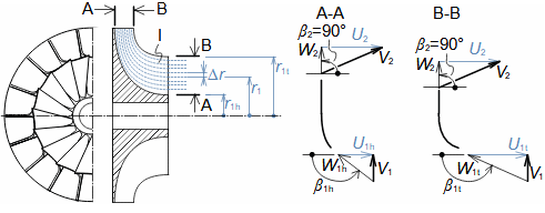
Problem 936/2:
Radial compressor leading edge
I-inducer; A-A section through blade at its base; B-B section through blade at its tip; Δr [mm] height of elementary stage.
Introduction to turbomachinery
page 28
  ~  
3D calculation
The 3D calculation is a complex numerical calculation of the turbomachine stage using advanced finite element methods (FEM) software. It usually takes into account velocity changes in the vicinity of the profiles (boundary layer effects). Before applying the 3D calculation, the approximate geometry of the stage calculated from the 1D or 2D calculation is already known.

References

ŠKORPÍK, 2023, Internal fluid friction and boundary layer development, Transformační technologie, Brno, fluid-dynamics.education/internal-fluid-friction-and-boundary-layer-development.html.
ŠKORPÍK, Jiří, 2024, Technická termomechanika, transformacni-technologie.cz, Brno, transformacni-technologie.cz/technicka-termomechanika.html.
ŠKORPÍK, Jiří, 2025, Aerodynamics of airfoils, Transformační technologie, Brno, https://fluid-dynamics.education/aerodynamics-of-airfoils.html.
MILLER, Rudolf, HOCHRAINER, A., LÖHNER, K., PETERMANN, H., 1972, Energietechnik und Kraftmaschinen, Rowohlt taschenbuch verlag GmbH, Hamburg, ISBN 3-499-19042-7.
©Jiří Škorpík, LICENCE