The steam turbines can be classification by their connection inside technological unit on condensing turbines, back-pressure steam turbines and turbines with a steam extraction:
A condensing turbine is a steam turbine that has a condenser at its exhaust. Usually minimum temperature of condensation of the water steam is about 15 °C (this temperature is a function of location and way of cooling of condenser). This temperature corresponds of the pressure of condensation about 0,002 MPa, therefore is used a term "expansion to vacuum". The condensation heat can be use for heating or for other purposes then the condensation temperature must be increased (for case heating on 80~90 °C), this state of the condenser is called suppressed condensation:
1.454 Flowchart of a condensing turbine.
The condenser is usually located just behind the turbine (outlet axial brachne of turbine) or under the turbine-the turbine must to lie on a concrete desk (the turbine has the side outlet). In case the air cooling condenser is the distance between the turbine and the condenser bigger (the air condensers are usually located on the roof of the machine room).
As back-pressure steam turbine are called the steam turbine that have the outlet to a steam piping or to the condenser but with pressure of condensation higher than 0,1 MPa:
 |
2.139 Flowchart of a back-pressure steam turbine. a steam piping. pi [Pa] the admission pressure; pe [Pa] back-pressure. The back-pressure is relation to a next use of the steam and this pressure can be higher than 1 MPa. The outlet steam can be fed other technologies or one can be used for the heating. |
The steam turbine with a steam extraction contains one or more an extraction of steam anywhere in front of the last stage of the turbine. The extraction steam expanded only between the admission pressure and the pressure in point of the steam extraction:
3.167 Types of the steam extraction of the steam turbine.
- 1The regeneration of heat in steam cycle
- The regeneration of heat in steam cycle is a process that increasing the efficiency of the cycle. At the regeneration of heat is condensation heat of the extraction of steam used for preheating of a feed water of a boiler.
The steam turbine with the controlled extraction is divided on two section. Both section are designed for the maximal flow mass rate through the extraction. It means that the mass flow rate through the turbine section behind the control valve is smaller than through first turbine section (in front of the control valve). If a consumer of the extraction steam is out of operation (season operation, service stop working and etc.) then the power output of turbine is reduced (approximately about 50% to 60 % of nominal power output of the turboset). There are steam turbines for the same mass flow rate in front of and behind the extraction but these turbines are expensive and if the consumer of extraction steam operates during full year this construction of the turbine is not need.
Both described types of extractions are often used together in one turbine. These types construction of the turbines are especially used in CHP plants. In these cases the uncontrolled extraction covers primary consumption of heat during the smallest consumption of heat. The CHP plant contains a reducing pressure unit which is connected in a bypass of the turbine (in case an accident of the turboset can continue the distribution of heat):
4.150 The flowchart of a CHP plant with a steam turbine.
The power output of CHP plant with the steam turbine corresponds with the connected of heat and steam consumers therefore their power output usually are to 100 MWe. The CHP plants are usually built in near the heat and steam consumers a often they are constituent part of an industry complex that has great consumption of heat and steam.
The power plants are usually built near source of a fuel or for other operation reasons near source of water (river, reservoir..), high voltage wires etc.
In the thermal power plants with stema turbines are installed the condensing turbines with the uncontrolled extractions of the steam for the regeneration of heat. A working parameters, design and flowchart of connection of this type of turbine is usually depended on type of the steam generator:
5.146 The flowchart for 200 MW Škoda thermal power plant.
- 2Reheating of steam
- The reheating of steam is other method which is used an increase efficiency of R-C cycle. The steam at the exit of the HP turbine casing is transfered again to the boiler (to the reheater), where it is heated almost on the admission temperature, but at lower pressure.
- 3Feed pump of boiler
- As a drive of feed pump is usually used an electric engine (so called electrically driven feed pump) for smaller unit or a small steam turbine (so called turbo-feed pump) for larger unit. The power input of the feed pump is small, therefore the steam turbine for drive of this pump has lower efficiency than the main steam turbine. If the turbo-feed pump efficiency is lower than product of efficiency of production electricity of the main turboset and efficiency of the electrically driven feed pump, then is taken into consideration of use the electrically driven feed pump.
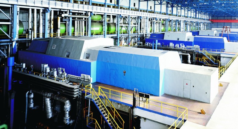
6.168 A arrangement of turboset 4x200 MW in machine room of the Dětmarovice thermal power plant. Figure: [9].
The most frequently type of nuclear reactor for a nuclear power plant is a pressurized-water reactor. The maximum temperature of water inside this type of nuclear reactor cannot be higher than the critical temperature of water. Actually the produced water temperature steam is usually much lower circa 320 °C max (usually <300 °C), because of heat transfer conditions and safe operation. The nuclear reactors are high resource of the heat and therefore the steam turbine in nuclear power plant can have 1500 MW power output:
7.149 A flowchart for 1000 MW nuclear power plant.
- 4Water trap
- The steam flow on the exit of HP casing contains some amount of water drops, because the steam is expanded from saturation state to wet steam state. These drops is necessary separated from steam flow inside the water trap–the reheater is not constructed for evaporation of water drop and the drops inside steam flow could cause a damage of the blades inside LW casing.
- 5Remark
- Although this is a power plant is possible some heat use for heating (e.g. heating of the power plant grounds or near housing estates).
The steam turbines up to 10-12 m their length are mounted on a base frame, that contains an oil system, electric switchboard and other accessories and an interface for a control system (limitation of the frame size are maximum transportation size capacity). In cases power output of steam turbines approximately up to 50 MW the base frame can contain the generator and in cases smaller power output (approximately up to 10 MW) even the condenser:
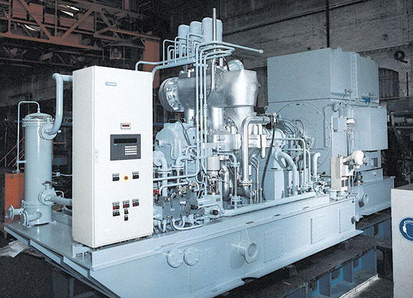
8.989 A turboset with a steam turbine and its accessories on a base frame-mounted design.
The steam turbine are also used as drive of ships and the first installation of steam turbine to ship Turbinia at end 19th was an impulse for bigger interest about the steam turbines. The production of steam for steam turbine on ship have been performed through a steam boiler on solid or liquid fuels. For production of steam can be nuclear reactors also that are designed for the ship applications. The nuclear propulsion increases a operating range these ships, e.g. at aircraft carrier up to 350 000 km. The power output of the steam turbines are in relation to function and displacement of the ship, e.g. Nimitz class of the aircraft carriers contains 4x steam turbine with 209 MW power output.
The turbines can directly power a screw propeller or electric generator and electric power is used for power the screw propeller through an electric motor (in case ship unit with a requirement on best regulation of speed or change of direction of rotation, e.g. icebreaker):
9.152 A nuclear icebreaker Yamal and simple schemes of connection a steam turbine on ships with nuclear propulsion .
Gas turbines and expanders
Gas turbines are usually used in heat power plant, CHP plant and as a drive of ships, as propulsion of airplanes etc. Through gas turbine is performed Brayton cycle. Gas turbines with open cycle and with combustion chambers (so called combustion turbine) can make up compact unit about power from 30 kW (micro-turbine) up to 500 MW. These units have also wide use at transportation thanks to its ratio power/size(weight)-other assumptions for this use are stepless power regulation and quick start and stop:
10.669 A gas turbine with combustion chambers (combustion turbine) and its accessories on a base frame-mounted design.
The combustion process inside the combustion chambers is continnously unlike a combustion process inside internal combustion engine, therefore the combustion process inside combustion turbine is more greener than for case ICEs. Nevertheless the combustion turbine consumes only noble fuel (clear fluid). An installation of the combustion turbine is fast, cheap and simple (in relation to unit with the steam turbine). They are also suitable for work in extreme surrounding conditions, thanka to their construction and size:
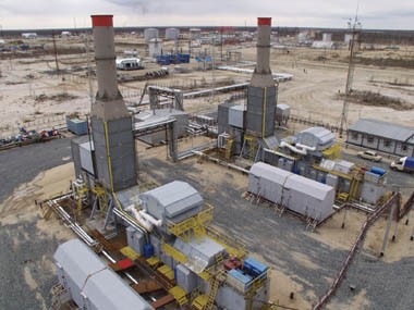 |
11.169 The combustion turbine are able to work in extreme surrounding conditions. This is a power plant in Severo-Gubinsky oil field (Russia-Jamal peninsula). Power output 2x4 MW. Natural gas as fuel. This power plant consist only of combustion turbine inside a container with regulation, air filter, connections and a chimney. Figure from [12]. |
Though the combustion turbine has a lot of advantages, so thermal power plants with combustion turbine is not widespread (as a backup source is the most popular application thanks to its quick start). The main reason for this fact is a high price of noble fuel (usually is used natural gas and petroleum derivatives; it being can burn less noble fuel, but it brings problems). For these reasons there are effort use maximum energy inside the fuel e.g. through regeneration of heat in Brayton cycle or use exhaust gas heat for heating or use their combination:
12.154 Flowcharts units with the combustion turbine with regeneration of heat and with a heat exchanger for heating.
Small combustion turbine with power output to cca 500 kW are called as micro-turbines, are usually used in CHP units which are characteristic with their quick start time, minimum maintenance requirements and small size...:
13.161 Single-line diagram of a small combustion turbine Capstone C30.
A disadvantage of the micro-turbines is their very higher operating speed (20 000 to 150 000 min-1). It has high requirements on bearings of the generator and relatively high financial requirements on the inverter and the rectifier. However the units with micro-turbine are relatively expensive and consumes only the noble fuels, therefore are used most frequently as backup powers, which are able quick start. Concurrently they are lighter than the backup units with piston combustion engines and therefore they are better for manipulations. The small units be can to assemble in groups that contain common a control system, it optimizes their operating properties.
Expansion gas turbines (the turboset does not contain any compression section) are usually called as turbo-expanders. It are frequently one stage turbines with one radial stage with axial exhaust especially if there is a requirement on wide scope of volume flow rate of the working gas and small enthalpy changes (the radial stages are less sensitive to change of the volume flow rate). For case higher working gas temperature are more suitable the turbo-expanders with axial stages (the axial stage is possible better cooling). The turbo-expanders are use as a reducing pressure unit on a pipeline, in the industry for liquefaction of gases and mix of gases with follow-up an extraction their component [2], in cryogenic industry (at the exit expansion of helium inside turboexpander can be only several tens of Kelvin [17], [31]). The power output of the turbo-expanders are about 100 kW to several megawatts.
The combustion turbine are used even for drive compressors of compressor stations on pipelines (they compensate of pressure drop). The compressor stations are built on distances 100 up 150 km for case transit pipelines and the mean pressure inside the pipelines is about 7,5 MPa and requirement of power input of the compressors is up 40 MW. As the fuel for compressor stations is used gas from the pipeline. If the power output of the combustion turbine is higher than power input of the compressor is can connect a generator on the other side of turbine for producing of electricity:
 |
14.666 Flowchart of a turboset with an combustion turbine and a turbocompressor for the compressor station Werne (Germany). 1 high-pressure turbine; 2 low-pressure turbine; 3 compressor; 4 pipeline; 5 wall that separates compressor section (natural gas section) from machine room of combustion turbine. The turboset contains two-shaft combustion turbine Pratt&Whitney FT8-55 about power output 26 MW. Other information about this compressor station is shown below. Information source [30]. |
The gas turbines are also components of Compressed Air Energy Storage (CAES) systems. This unit contains a turbocompressor powered by an electric motor, a storage tank on compressed air (it can be an excavated underground mine or others types of underground space) and a gas turbine with a combustion chamber. Its function is follow: at surplus of electricity in electrical grid the drive of compressor is switch (air is compressing to the tank). On the contrary the combustion chambers of the turbine is feed by the compressed air if electricity is lack in the electrical grid. The exhaust from combustion chambers is being expanded inside the turbine which drives the electric generator. The flow of air from the tank can tear off dust and dirt which can damage the blades of the turbine, therefore these blades must be especially modified and often controlled. This system has quick start of accumulation mode even production mode. These units for accumulation of electricity have approximately about 50% turnaround efficiency. The efficiency can be increasing through accumulation of compression heat-regeneration of heat (AA – CAES – Advanced Adiabatic CAES). This extension could increase the turnaround efficiency on 70 to up 75 % [4], [15, p. 171] without the combustion other fuel in front of the turbine. In currently this system is tested by RWE company in Germany [3]:
15.720 A flowchart of accumulation power plant AA-CAES type.
The combustion turbine are of great important in aviation, where is used as propulsion unit:
16.164 A turbo-fan jet engine.
A force that is developed by the jet engine is called a thrust. The thrust of the jet engine is defined same as for case the thrust of propeller propulsion. In this case the mass flow rate is upper about a mass flow rate of the fuel that being injected to the combustion chambers. The thrust is developed by flow of gas at the exit of the engine (the exhaust gas that flows through core of engine + the air that flows through bypass). The efficiency of jet engine is defined as the internal efficiency of propeller only an input power of propeller is substituted by input of chemical energy in the fuel. The bypass increasing the total flow mass rate through engine [23, p. 177], but it decreasing the average velocity of the working gas at the exit of the engine. Therefore the jet engines with higher mass flow rate through bypass are convenient for lower fly speed and on the contrary. A ratio of the air flow passing through the bypass and the air flow passing through the core of engine (combustion chamber) is called the bypass ratio [23, p. 168] (the bypass ratio is usually 1:8 for case turbofan engine of passenger aircraft). The definition of propulsion efficiency of the jet engine is same as propulsion efficiency of a propeller drive engine and it is ratio between work of the thrust per one second of flight and the change kinetic energy of air and fuel:
17.176 Main types of jet engines and the definitions their efficiency.
For higher efficiency of the jet engine at change of operation conditions of are used multi-shaft engines:
18.664 A flowchart of a two-shaft jet engine.
The power and other parameters of jet engine are in relation to requiring airspeed of an airplane and its operating altitude. In currently the jet engine turbofan Trent 900 Rolls-Royce has highest from all thrust about 360 kN, this engine is used even on Airbus A380. The Concorde had used 4xjet engine turbojet Olympus 593 Mrk610, the thrust of this engine was about up 170 kN and at 2 Ma (maximum speed) about 45 kN (producer Rolls-Royce/SNECMA). The jet engine of Global flyer6 (Williams international, typ fj44-1) can be an example of small engine, this engine has 6,7 to 8,5 kN of the thrust. The jet engine of Marabu7 airplane (PBS Velká Bíteš) is an example micro engine TJ100 with 1 kN of the thrust.
- 6Global flyer
- The first aircraft with the jet engine, that flew around the World without refueled. This event has become in the spring of 2005. The pilot Steve Fosset [32] also became the first man to circumnavigate the world in the aircraft itself.
- 7Marabu
- The Marabu is an experimental aircraft, that had developed by Brno university of technology [10]. This aircraft contains combined propulsion system, that contents combustion engine with a pusher propeller and small jet engine - the engine is fitted to the frame on left side of the aircraft. The weight of jet engine is 19 kg [17].
For propulsion of helicopters through the combustion turbine is used similar principle as for turboprop. In this case the combustion turbine drives a main rotor and a tail rotor through a gearbox. For held stability be can use a flow of the air by nozzles, that are fed from turbocompressor section of the combustion turbine. The power output of the helicopter turbines is approximately 100 kW up 800 kW and one helicopter can contain even several engines.
The combustion turbine for aircraft are under strong and regular controls also they have limited service life due to strict legislation. This service life is very short time in relation to technical service life. Therefore these turbines are in good condition after exclusion from airplane and therefore they are use usually in power industry yet. These jet engines must be modified for stationary operation and production of mechanical energy (problem high shaft speed, removed of the bypasses, addition others turbines stages and turbocompressors stages etc.), such turbines are called Aeroderivatives. The aeroderivatives reach up 40 MW power output (for cases radically modified aeroderivatives with high efficiency even over 100 MW). Advantages of the aeroderivatives is quick the start (thanks to lightweight their rotors) and lower cost for case small power output. The aeroderivatives with higher power output can be more expensive but one have higher efficiency8.
- 8Efficiency of aeroderivatives
- The efficiency is increased through methods that are shown in article 27. Gas turbine in technological unit. These changes contains inter alia addition of others casings (with compressor and turbine stages), which increases the cost of the aeroderivatives.
 |
19.665 Flowchart of simple aeroderivative. a core of the aeroderivative (combustion turbine from jet engine); b expansion turbine for use of an gradient of enthalpy which is equal to the kinetic energy of exhaust gas from core of the aeroderivative. The combustion turbine for the airplane do not contain horizontal assembly surfaces (need weight savings) and a montage is done in axial direction through vertical assembly surfaces. In these cases is needed special assembly tools for the montage and removal which are usually used at the maintenances of the airplane. |
The internal combustion engine are also used as a drive of ships and land vehicles (locomotives, personal cars..) most often at army vehicles (tanks). Main reasons of use the internal combustion engine for drive of land vehicles is its low weight in relation to its power output:
20.165 Examples of drives with combustion turbine for ships and personals cars.
- 9Turboset LM2500 on ocean liner Queen Mary II
- The Queen Mary II is longest transatlantic ocean liner on the world about 345 m length and its displacement is 75000 tonnes. Its drive system contains a combination of ICEs and two units LM2500 which produce electric energy for electric drive screw propellers. The set screw propellers-electric motor are located inside a nacelle that is outside of the hull. The total of power output of the ship drives is 117,2 MW of which 50 MW produce LM2500 units. The unit LM2500 is formed by an aeroderivative from GE CF6 – 6 jet engine about 234 kN thrust (this jet engine is also used on an airplane Boeing 747). The turbine and the generator are mounted to especial box which is soundproof and is equipped antivibrating blocks. The flow channels of turbine are made of material which is resistant on surroundings of the sea air. The units LM2500 are located on the upper deck near a suction an chimney. The heavier ICEs are located under center of gravity of the ship inside of the hull.
- 10Turbine drive of personal car Chrysler (1963)
- The turboset is two-shaft and is composed from the combustion turbine with one-radial stage of compressor and one-axial turbine and a drive tubine with one axial stage (the drive turbine section has opposite rotation than combustion turbine). The regulation of the power output is performed by a change of flow mass rate of the exhaust through the regulation nozzle. The regeneration exchanger rotates through high-pressure volume of compressed air even low-pressure volume of the exhaust. The nominal power output on the shaft is 130 hp at the rotation speed 3 600 rpm, the maximum rotation speed are 44 500 rpm. More information about turbine drives of the personal cars are shown e.g. in [28], [23].
A gas turbine is also a component of a rocket engine liquid propellant. In these cases the turbine drives a oxidizer pump and a fuel pump through which is held required pressure inside combustion chamber (e.g. the operating pressure of the combustion chamber of SSME rocket engine of spacecraft Space shuttle has been 20,3 MPa and power output of turbine of hydrogen pump has been up 56 MW [25, p. 25], [29]).
The exhaust heat at the exit of the combustion turbine is can used for production of water steam, similar as for production of heat water on the Figure 12. This steam can be used inside a steam cycle. The combination Brayton and steam cycle is called Combined cycle gas turbine (CCGT) and it significantly increases efficiency of transformation energy of fuel to electric energy on level upper 55 % (in currently /2012/ 60 %).
Combined cycle gas turbine (CCGT)
According the analysis of heat cycles for their maximum thermal efficiency is needed highest possible the mean temperature of input heat to cycle and lowest possible the mean temperature of rejection heat of cycle. The cycle of the combustion turbine is compatible with the first requirement and steam cycle is compatible with the second requirement. A combination of these two cycles arises the CCGT:
21.155 A flowchart of the combined cycle gas turbine and its illustration in T-s diagram.
At combustion of the same amount of fuel inside CCGT is produced more work than is work of separate the combustion turbine. For higher power output of CCGT power plant be can used combustion other fuel in the steam boiler where is used oxygen in exhaust gas of the combustion turbine (so called additional heating). The additional heating decreasing the efficiency, because it is decreased portion of power output of the combustion turbine on power output of CCGT.
A optimal calculation of the steam part of CCGT is derived from mass flow rate of the exhaust gas at the exit the combustion turbine and their temperature T4. From this description is evident that the maximum steam temperature Tb must be lower than the temperature of exhaust gas T4 about a difference ΔT1 (this temperature gradient inside heat exchanger is necessary requirement - superheater of the heat recovery boiler). The temperature of saturation of steam Tb' is given the necessary temperature difference ΔT2 inside an evaporator of the boiler. From law of conservation of energy is evident that heat which corresponding to temperature change of exhaust gas between temperature T4 and temperature T5' is equal heat which correspond to enthalpy change of steam between states b and b'. Heat which is correspond to temperature change of exhaust gas between temperature T5' and temperature T5 is equal heat which correspond to enthalpy change of water between states b' and a (if the steam cycle contains a regeneration heat then is consumption of heat lower between these temperatures). The minimum temperature difference between exhaust gas and feed water of the boiler is ΔT3. The result of the optimal calculation is the steam cycle about maximum possible power output. For maximum power output is usually used multi-pressure steam cycle, which is described in chapter 25. Steam turbine inside CCGT unit.
I describe here the Red mill heat power plant in Brno as an example of the CCGT unit which contents double pressure cycle. Total electric power output of this plant is 94 MW, power output of gas turbine is 70 MW, total heat power output is 140 MW. The steam part: 100 t·h-1, 6,84 MPa, 500 °C, 0,92 MPa. The heat power is transfered by hot water (125 MW) and by steam (15 MW), efficiency of electric power output is 47,5 %, total efficiency is 89,0%, power to heat ratio is e=0,68. The exhaust of the combustion turbine is connected with the steam recovery boiler through an exhaust pipe, which contains own a chimney. Thanks to this chimney is possible operation the combustion turbine without the steam part of unit (e.g. if there is a require on faster start of production of electricity):
22.157 Flowchart of steam part of CCGT power plant Red mill.
The steam turbine in Red mill contains one controlled steam extraction and one uncontrolled steam extraction. The steam from the controlled extraction is used for feeding the steam pipe of steam consumer, but if steam pressure inside the steam pipe is higher, then the steam flows through a valve of controlled extraction to turbine and mass flow rate of steam is maximal. The uncontrolled steam extraction is used for feeding a heater of hot water during high consumption of heating:
23.670 Back-pressure double-pressure steam turbine with one controlled extraction and one uncontrolled extraction, type G40 (ALSTOM Power in Brno).
CCGT plant are worldwide thanks to their high efficiency and their short building time. CCGT units are also used as a drive of ships11.
- 11CCGT drive of ships
- In these cases, the steam part is pasted behind the head drive unit, which is ICE or a combustion turbine. An efficiency these combined units can be up 51,5 % [1, p. 32]. For these purposes are most useful turbosets with steam turbine on a base frame, which contains a condenser also.
Turbocompressors
The turbocompressors are used where there are requirements on cleanliness of working gas, on high service life or on high volume flow (up 3 000 000 m3·h-1). The turbocompressors are also lighter than reciprocating compressors. There are the turbocompressors which have pressure up 100 MPa at the outlet (possibilities individual types of the turbocompressors as function pressure at their exit and capacities are shown on a graph in [16, p. 60]). The turbocompressor are able to working at very low temperatures, e.g. at a cryogenic application is temperature of helium vapor only 3,5 K [17]. They are used in mining and engineering industry, where is high consumption of compressed air for pneumatic drive, in chemical industry, in cooling technology, in compressor stations and compression parts of most types of gas turbines..:
24.160 Compression station in Werne (Germany).
Similar types compressors as in transit stations are also used in industry to ensure circulation of a working gas on a technological unit. Therefore these types compressors with high pressure at the inlet and small pressure ratio are called circulation compressors [26, p. 16].
For higher internal efficiency of compressor of multi-stage compressor is able to use intercooling:
25.671 Principle compression with intercooling and an axial section view of 6-stages radial compressor with one extraction for intercooling.
It is evident that maximum work Δai is reached at isothermal compression. Therefore the intercooler are usually used behind the greatest number of stages, but are used other ways cooling of compressors.
There are reversible compressors which are special type used in gasholder units. This type compressor can be able to operate as a compressor and a turbo-expander. The reversible compressors are connected through a coupling with electrodrive which be able to worked as an electric generator [6].
Compressors with atmospheric pressure at their inlets and with pressure ratio to 3 are called blowers respectively rotary blowers for cases turbomachines. The rotary blowers are usually small one-stage radial compressors with an electric drive. The blowers are used for increasing air pressure on the inlet of ICE. In this case the blower can be powered by a mechanical transfer from shaft of the engine or usually by a small gas expander in which expands an exhaust gas from the exhaust of the engine. This turboset is called turbocharger:
 |
26.163 Flowchart the set of ICE with gaseous fuel and a turbocharger. 1 piston combustion engine; 2 cooler of fuel mix; 3 inlet of air; 4 natural gas (a fuel); 5 turbine section of turbocharger; 6 compressor of turbocharger; 7 spark plug; 8 catalyst; 9 mixer; 10 cooling loop of engine. |
The capacity of turbochargers is from 500 m3·h-1 of air (ICEs about 100 kW power output), up 20 000 m3·h-1 of air (stationary ICE between 5 up 7 MW power output), for piston combustion engine as marine propulsion can be use turbocharger with more capacity. More information about the turbochargers and their regulation is shown in [28].
Temperature influences on design of heat turbines
A high quality of blades materials and treatment its surface (see chapter 15. Materials of turbomachines) need not be sufficient for high temperature resistance particularly for first stage heat turbines such as the combustion turbines. In the reason is nessary used an active cooling of the blades. The types of the active cooling is e.g. cooling of blade roots or cooling the core of blade through small channels. As cooler is used air (combustion turbine) or water [11, p. 931] (for case steam turbines):
 |
27.682 Blades with cooling channels of an combustion turbine MS5002 GE. The cooling air is extracted in some part of compressor (for first stages of expansion part of the turbine is extracted cooling air behind last stage of compressor). The cooling air is flowed to the stream of expanding exhaust gas through holes at end of pressure side of the blade. The surface of blades must be coated by corrosion resistance layer on its cooling side. Figure from [15]. |
The construction of the combustion chambers must be cooled also. It is realised by combustion air which flows through the construction.
References
- TŮMA, Jan. Rotterdamský přístav se posouvá do moře, Technický týdeník, č. 11, 2011. Praha: Business Media CZ, ISSN 0040-1064.
- Natural gas processing, Wikipedia, [2011]. [on-line], http://en.wikipedia.org/wiki/Natural_gas_processing.
- ADELE – Adiabatic compressed-air energy storage (CAES) for electricity supply, [2011]. [on-line], http://www.rwe.com/web/cms/en/365478/rwe/innovations/power-generation/energy-storage/compressed-air-energy-storage/project-adele.
- Energy Storage Power Corporation, [2011]. [on-line], http://www.espcinc.com.
- TŮMA, Jan. Velkokapacitní zásobníky spolehlivě uskladní přebytky elektřiny – Tlakovzdušné akumulační elektrárny na obzoru, Technický týdeník, č. 6, 2011. Praha: Business Media CZ, ISSN 0040-1064.
- Efektivní reverzační turbokompresor, Technický týdeník, č. 1, 2011. Praha: Business Media CZ, ISSN 0040-1064.
- IBLER, Zbyněk, KARTÁK, Jan, MERTLOVÁ, Jiřina, IBLER, Zbyněk ml. Technický průvodce energetika-1. díl, 2002. 1. vydání. Praha: BEN-technická literatura, ISBN 80-7300-026-1.
- IP Rotor Cooling, [2011]. Popis základních atributů konstrukce parních turbín společnosti Mitsubishi Heavy Industries, Ltd. http://www.mhi.co.jp/en/products/detail/steam_turbine_design_topics.html.
- ČEZ, a.s., 2011. Majitel a provozovatel elektráren. Adresa: Praha 4, Duhová 2/1444, PSČ 140 53, Česká republika, http://www.cez.cz.
- Letecký ústav na FSI VUT v Brně, [2012]. Pracoviště, kde byl navržen a postaven exerimentální letoun MARABU. Adresa: Fakulta strojního inženýrství, Vysoké učení technické v Brně, Technická 2896/2, 616 69 Brno, http://lu.fme.vutbr.cz.
- MILLER, Rudolf, HOCHRAINER, A., LÖHNER, K., PETERMANN, H. Energietechnik und Kraftmaschinen, 1972. Hamburg: Rowohlt taschenbuch verlag GmbH, ISBN 3-499-19042-7.
- CSC Iskra-Energetika, 2012. Inženýrská společnost v oblasti energetiky. Adresa: 28, Vedeneev Str., Perm, Russia, 614038. Web: http://www.iskra-energy.ru.
- Ecomagination, 2012. Webové stránky společnosti General Electric Company zaměřené na prezentaci produktů. Web: http://www.ecomagination.com.
- MATTINGLY, Jack, HEISER, William, PRATT, David, Aircraft Engine Design, 2002. Second edition. Reston: American Institute of Aeronautics and Astronautics, ISBN 1-56347-538-3.
- MS 5002 Gas Turbine a Through D Evolution, [2011]. Propagační článek společnosti GE. http://www.ge.com.
- BECKMANN, Georg. GILLI, Paul. Thermal Energy Storage, 1984. Wien: Springer-Verlag, ISBN 3-211-81764-6.
- První brněnská strojírna Velká Bíteš, a.s., [2012]. Výrobce a dodavatel malých plynových turbín, kryogenních turbokompresorů a malých parních turbín. Adresa: Vlkovská 279, 595 12 Velká Bíteš, http://www.pbsvb.cz.
- DANILOV, Alexandr. Пpocтopы apктики, В мире науки, 2006. Ruskojazyčná verze časopisu Scientific American. Moskva: Адрес: 119991 г. Москва, ГСП-1, Ленинские горы, МГУ, д. 1, стр. 46, офис 138.
- Nuclear Propulsion, Federation of American Scientists, 2000. Washington, DC: 1725 DeSales Street, NW 6th Floor, 20036, http://www.fas.org/man/dod-101/sys/ship/eng/reactor.html.
- LAVERY, Brian. Lodě, 2005. 1. vydání. Praha: Euromedia Group k. s., ISBN 80-242-147-7.
- Siemens AG, 2011. Výrobce a dodavatel mnoha týpů tepelných turbín a turbokompresorů. Web: http://www.siemens.com.
- Capstone Turbine Corporation, 2011. Výrobce a dodavatel malých plynových turbín se spalovací komorou. Web: http://www.capstoneturbine.com.
- BATHIE, William. Fundamentals of gas turbines, 1984. John Wiley&Sons, Inc. ISBN 0-471-86285-1.
- General Electric Company, 2011. Výrobce a dodavatel mnoha typů tepelných turbín a turbokompresorů. Adresa: Fairfield, CT 06828, United States. Web: http://www.ge.com.
- RŮŽIČKA, Bedřich. POPELÍNSKÝ, Lubomír. Rakety a kosmodromy, 1986. Vydání 1. Praha: Naše vojsko.
- CHLUMSKÝ, Vladimír, LIŠKA, Antonín. Kompresory, 1978. 1. vydání. Praha: SNTL.
- History of Chrysler Corporation – Gas Turbine Vehicles, 1979. Prepared By Technical Information Engineering, 42 stran. Web: http://www.turbinecar.com/misc/history.pdf.
- JAN, Zdeněk, ŽDÁNSKÝ, Bronislav. Automobily – Motory, 2010. 6. vydání. Brno: Avid, spol. s.r.o., ISBN 978-80-87143-15-5.
- SUTTON, George. BIBLARZ, Oscar. Rocket propulsion elements, 2010. New Jersey: John Wiley & Sons. ISBN 978-0-470-08024-5.
- MAN Diesel & Turbo SE, [2012]. Výrobce a dodavatel mnoha typů tepelných turbín a turbokompresorů. Adresa: Augsburg, Stadtbachstrasse 1, D-86153 Augsburg, Deutchland. Web: http://www.mandieselturbo.com.
- KAPICA, Pjotr. Experiment, teorie, praxe, 1982. 1. vydání. Praha: Mladá fronta. Překlad z ruského originálu Эксперимент. Теория. Практика, 1977.
- FOSSET, Steve. Lovec větru-vlastní životopis, 2008. Řitka: Daranus, s.r.o. ISBN 978-80-86983-59-2.
Citation this article
This document is English version of the original in Czech language: ŠKORPÍK, Jiří. Tepelné turbíny a turbokompresory, Transformační technologie, 2011-02, [last updated 2014-02]. Brno: Jiří Škorpík, [on-line] pokračující zdroj, ISSN 1804-8293. Dostupné z https://www.transformacni-technologie.cz/23.html. English version: Heat turbines and turbocompressors. Web: https://www.transformacni-technologie.cz/en_23.html.